Embedded Programming
What could i learn on this datasheet ??
Starting this week with a particular mind, enclosing at my home with my wife & my son for the COVID Quarantine....
Hopefully the FABACADEMY is already a remote curse ^^.
Ok let's take a look of this assignement. On the week 4 & 6 i worked with a Attiny 44A, it's the reason i selected this MCU Datasheet.
A datasheet is a quite dull-reading document generaly composed by a hundred or more pages explaining all the MCU composition & all is functions.
Boring but very important to understand what we could or couldn't make on a embedded program.
According to my level of understanding the datasheet give me Two really important information:
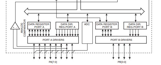
- - The Block Diagram (explain to us how the MCU interfacing between is different inside element)
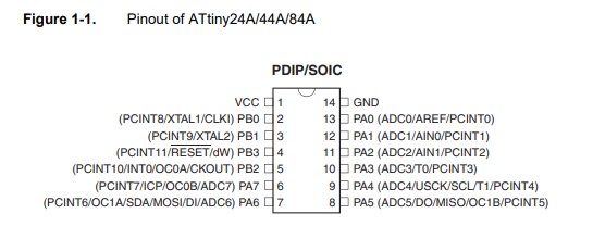
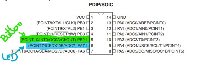
- - The Pinout distribution.

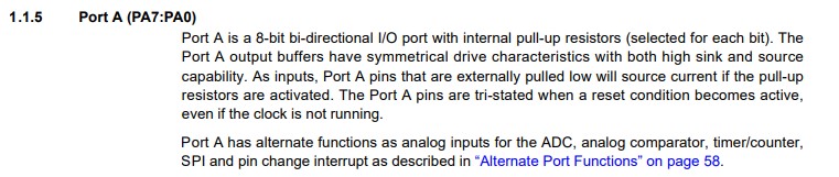
We could also find on the datasheet a detailled description of each port, each function, each option of the MCU.
Programming:
I worked this week we the modification of the ATtiny 44 Hello-board i made on the electronique design week.
I already have start to program it on the last week with the "Echo.c" programme.
Now i'm going to play with the LED i add on the board.
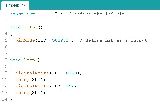
I start by writting a simple code on the Arduino IDE to make my LED Blink!.
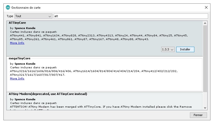
And i select the good kind of board after installing the ATTinyCore using the Boards Manager in arduino. (instalation Link)
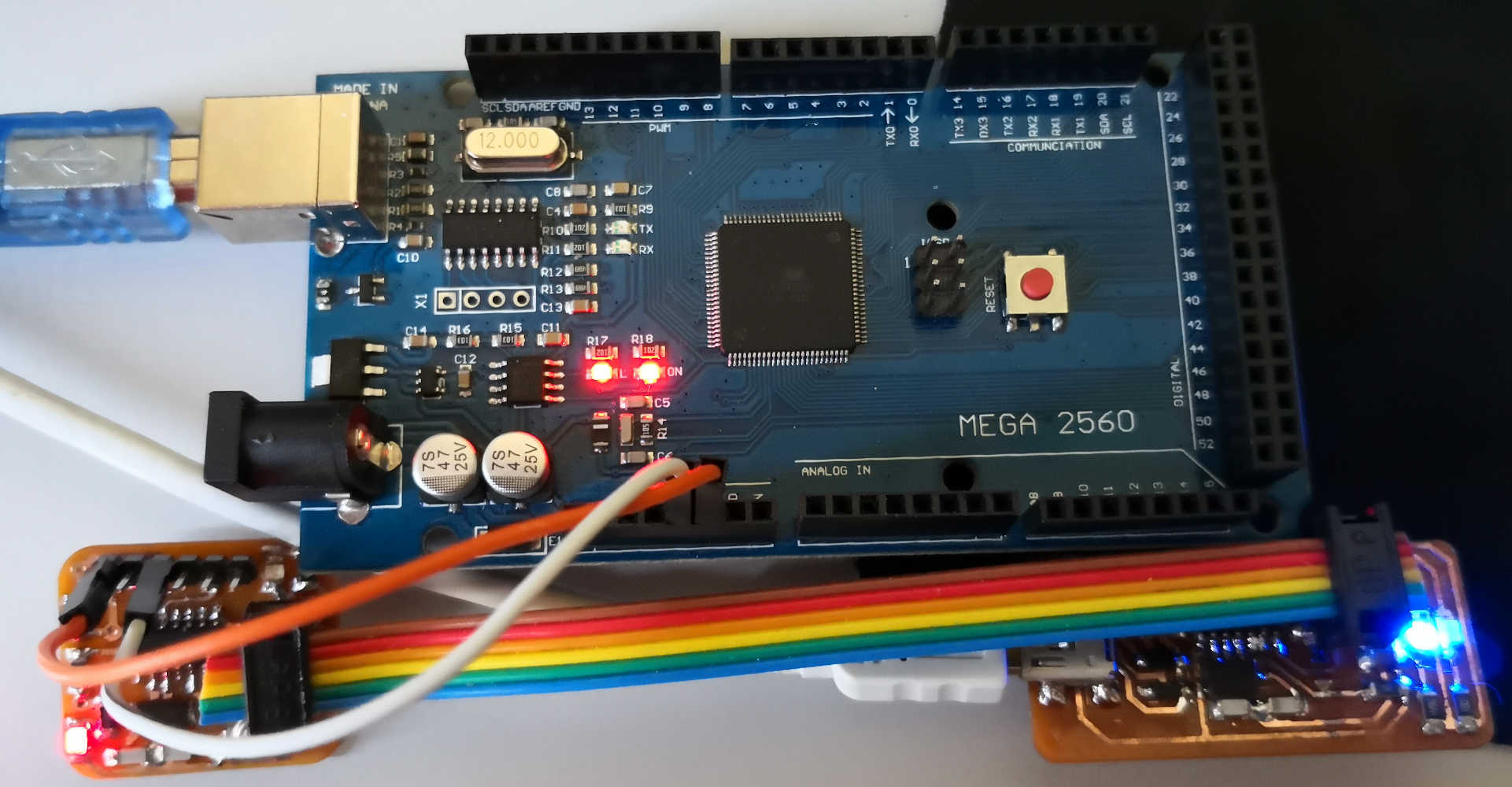
After writing this code, i set up my board with my FabISP & add a external supply with a arduino. Now i send my code with Arduino IDE in my programmer.
And It's Work ^^ (code here)
Try PlatformIO
To see another programming environement i going to try PlatformIO is a free, open source, and MIT licensed toolset for embedded C/C++ development.
It's working as an extensions on "Atom" or "VScode" for this assignement i'm gonna use it on VisulaStudio Code plateform (VSCode is a multi language code editing software, built on
open source.)
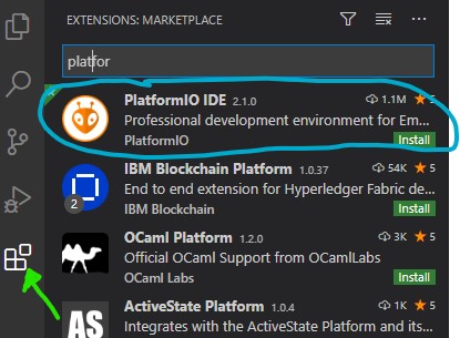
After installing VSCode just select the extensions chearch & install PlatformIO.
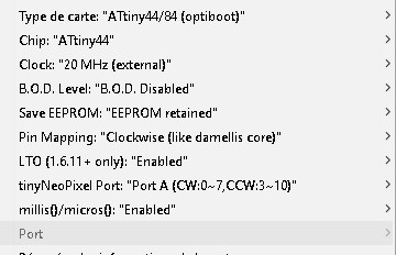
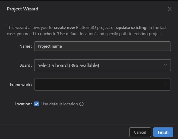
On the welcome page of PlatformIO i select New project and select the "Name" of my project & the board i want to work with (ATTiny 44 again) for this board the framework is autoselected by the soft (Arduino framework)

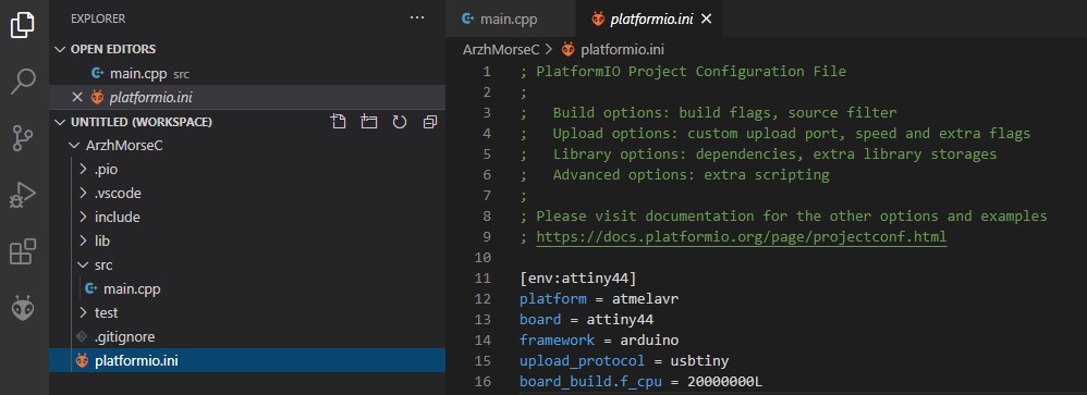
In the root of the Platformio project there is a file named platformio.ini. This file contains the configuration informations as :
- the type of chip: platform = atmelavr
- the chip model: board = attiny44
- the operating framework:framework = arduino
- the programmer used:upload_protocol = usbtiny
- the clock used: board_build.f_cpu = 20000000L (20Mhz)
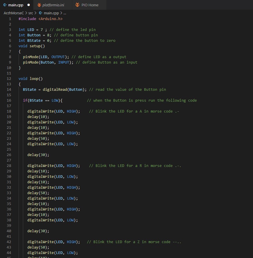
After the setting let's place to coding. This times let's have more fun. For this i programming my board to blink my pseudonym "ARZH" in Morse code
According to the International code that give .- .-. --.. .... I also want my board start to blink when i press the button;
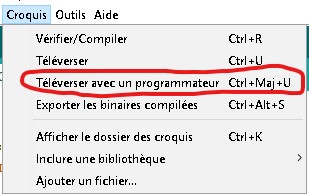
When i finish to write my code, i try to Upload it on my board when i saw a warning message on the Terminal

Aparently by default PlatformIO use CounterClockwise pinout for some boards, result = After the Upload nothing work on my board (logical).
So i have to modify the pin number i define on my project as i could find on this shem:
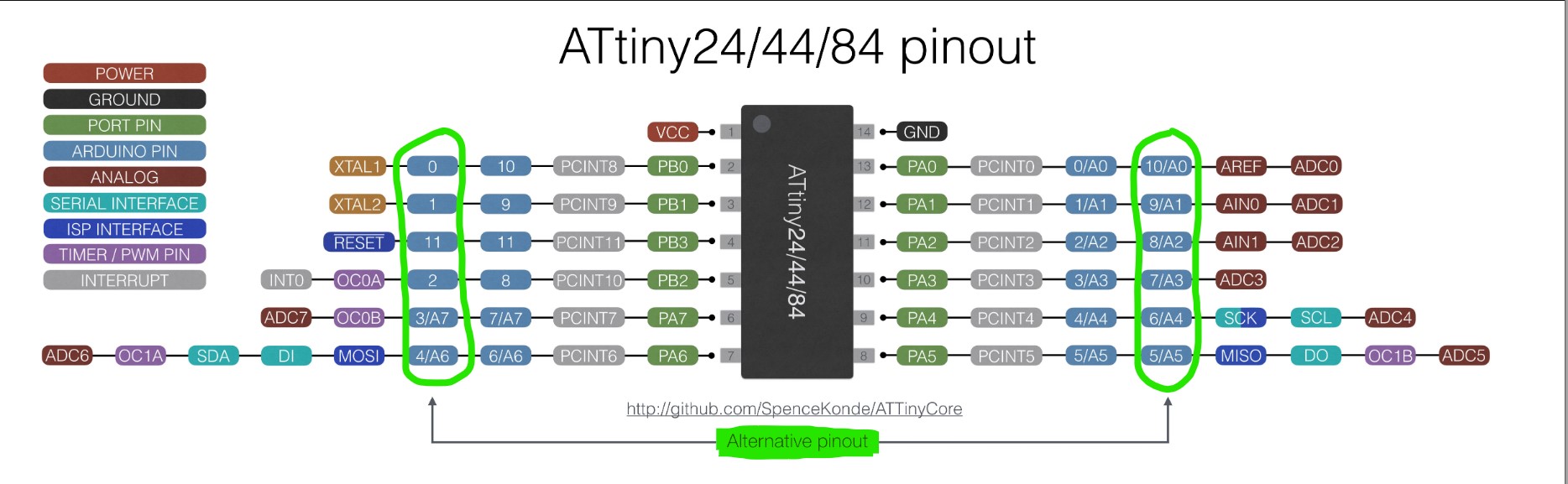
And it's work perfectly: Code here
Let's try some C
Now i want to programme my LED blinking when i push the button, let's go to programme this in a different way.
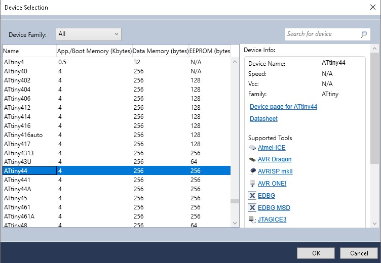
I write my code in C using ATMEL-Studio.
First time i programming on C, for this exemple i take inspiration on Marta Verde a 2016 Fabacademy student.
This programming introduction PDF was really helpfull.
Need the Port section of the datasheet to understand what i do ^^.
After Writting my code i use the Toolchain with avrdude & a makefile in my GITBASH to transfer it on my board
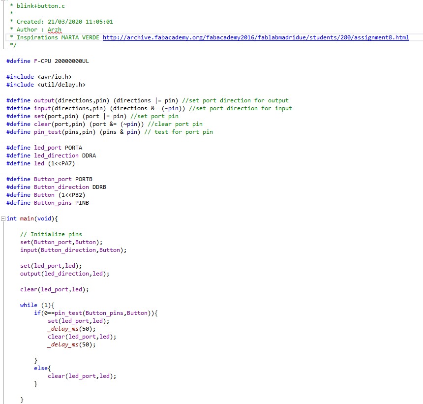
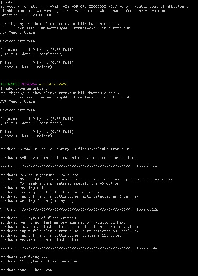
And it's Work Again..... (Code & Makefile here)
Some explanation:
For going more deep on the code & the understanding of it, let's put some code near the datsheet:
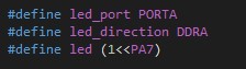
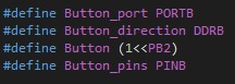
For the MCU on my board the pin i use for the LED is the PA7 and for the Button is the PB2 pin
On the Bottom of the "Blockdiagram" we have the Ports & Data register on this we could see who is the Port attribute for each pin we want to use.
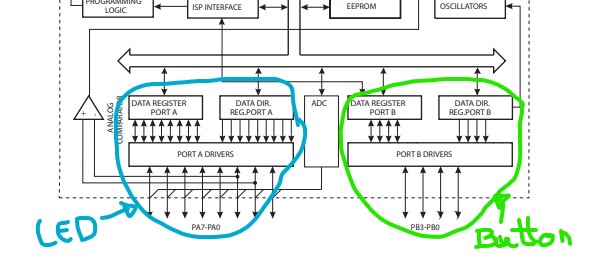
With all this informations we could now, define the right port, direction & pin for each pin we gonna use.
With the fun mood i have when i worked on morse code i do another one in C language to blink the word "FABACADEMY"
Or on morse Code ..-. .- -... .- -.-. .- -.. . -- -.--
Here you could find the files and let's go for a short video to show you the result
Group Assignement:
For this week, the Group assignement is to compare workflows and programation for other architecture.
Due to the surrending of Alban, i'm without group. But i could compare with the work i do for my final project.
On my project i worked on a Esp 8266 & some ATTiny 1614 let's go talk about the workflows of thiis MCUs
The ESP 8266 is a 32 bit MCU with a integrated 2.4 GHz Wi-Fi, could be used for many thing with UART, GPIO, I2C, SPI....
You could use it for make a wifi connected product & directly use it by connecting on web page on it....
For my case i programme it using the Arduino Framework, for this i have to install the ESP8266 core like previously with the attiny core. And setting up for your MCU.
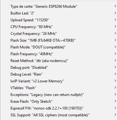
As me you could need to use on your programme some .HTML / .CSS / .TXT / .PNG / .BMP files, for this follow this Tutorial to install the Filesystem Uploader.
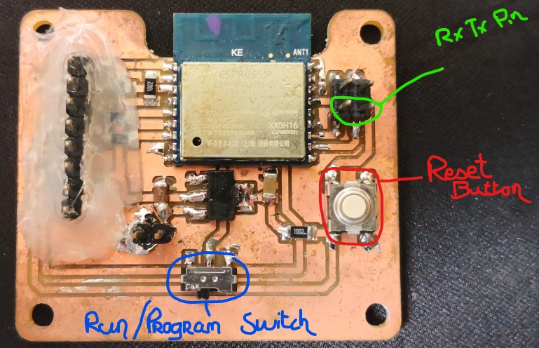
When you finish to code your programme you just have to Upload it to your board connected via UART after place the Run/Programming Swith on programming, When is connected to the terminal push the reset button & let's go.
The following video is a perfect showing of the workflow by Neil
More information about my ESP8266 board Here
The 1614 is one of the new generation of 8bit AVR MCU (AVR 0,1-series), like the ATTiny44 he come on a 14 pin SOIC but he have 16KB memory and a internal clock up to 20MHz
On the arduino IDE we have to install the MegaTinyCore from Spence Konde.
The principal difference on workflow between this generation & the old ATTiny one is, they use UPDI programation instead of the classic ISP.
UPDI use for the code upload a unique pin (and a shared GND) instead of the classical 6 pin for ISP.
Spence Konde give to us a technique for make a cheap one using a arduino board. Let's check this:
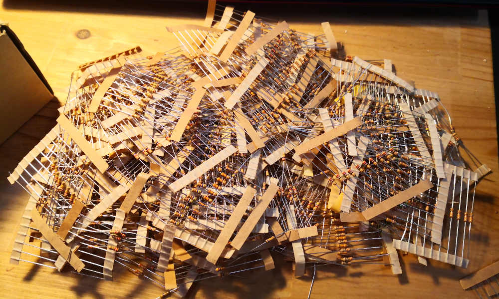
For Start i need an arduino & a 470Ω resistor, fun fact a recently accident happen on the resistor storage, so all the resistor are on a box.
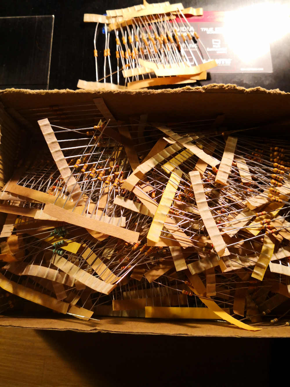
Let's go find a needle in a resistorstack: (i use this helpfull sheet to guide me)

Ok, i have my resistor, now i need to prepare the arduino board.
- The UPDI programmer sketch can be found here: https://github.com/SpenceKonde/jtag2updi Download and extract, or clone the repo to your local machine.
- Browse to the download location and open the jtag2updi folder
- Open the sketch jtag2updi.ino and upload it to your Arduino. The .ino file itself is empty, and this is fine - all the code is contained in other files in the same folder, but the empty .ino is needed so that the IDE can compile it.
When the arduino is ready let's connect it to the ATTiny board:
- Connect Ground of Arduino to Ground of the ATTiny
- Connect Pin 6 of the Arduino to the UPDI pin of the ATTiny via the 470Ω resistor.
- Unless the ATtiny has it's own power supply, connect 5v pin of the Arduino to the Vcc pin of the ATtiny
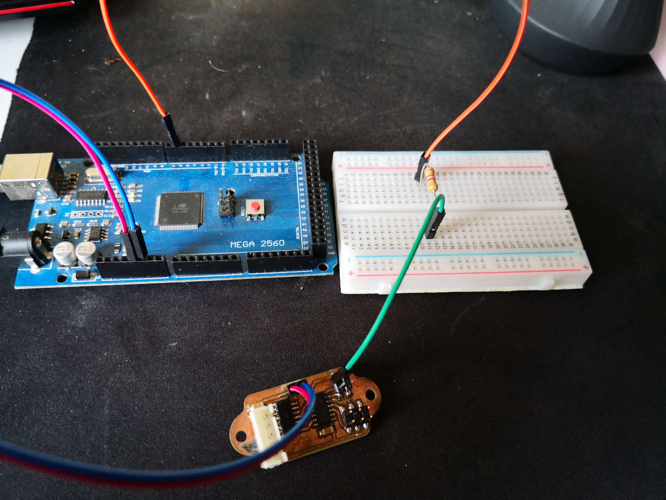
Now, i'm able to select an ATtiny megaAVR series board from Tools -> Board, and upload a sketch via the IDE.(be sure to select the jtag2updi (megaTinyCore) programmer from Tools -> Programmer menu)
Another option to UPDI upload
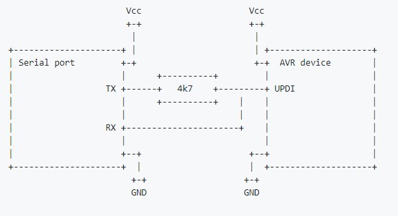
During my different expereince on ATTiny 1614 programming i also try the Neil's technique to upload via UPDI. This technique use PyUPDI a Python UPDI driver for programming "new" tinyAVR and megaAVR devices using a standard TTL serial port.
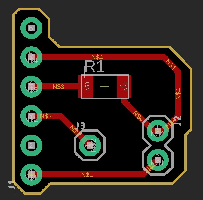
following the schematics on the PyUPDI github i qwickly made a FTDI cable/board adaptator using a 4K7Ω SMD resistor.(Board files Here)

First you have to have Python installed on your computer, if not youy could find it here: https://www.python.org
When Python is on your systeme you just have to use your terminal for installing "pyupdy.py" directly with this commande:
pip install https://github.com/mraardvark/pyupdi/archive/master.zip
Connect your Board to your computer using an FTDI adaptator & the small boards i previously made:
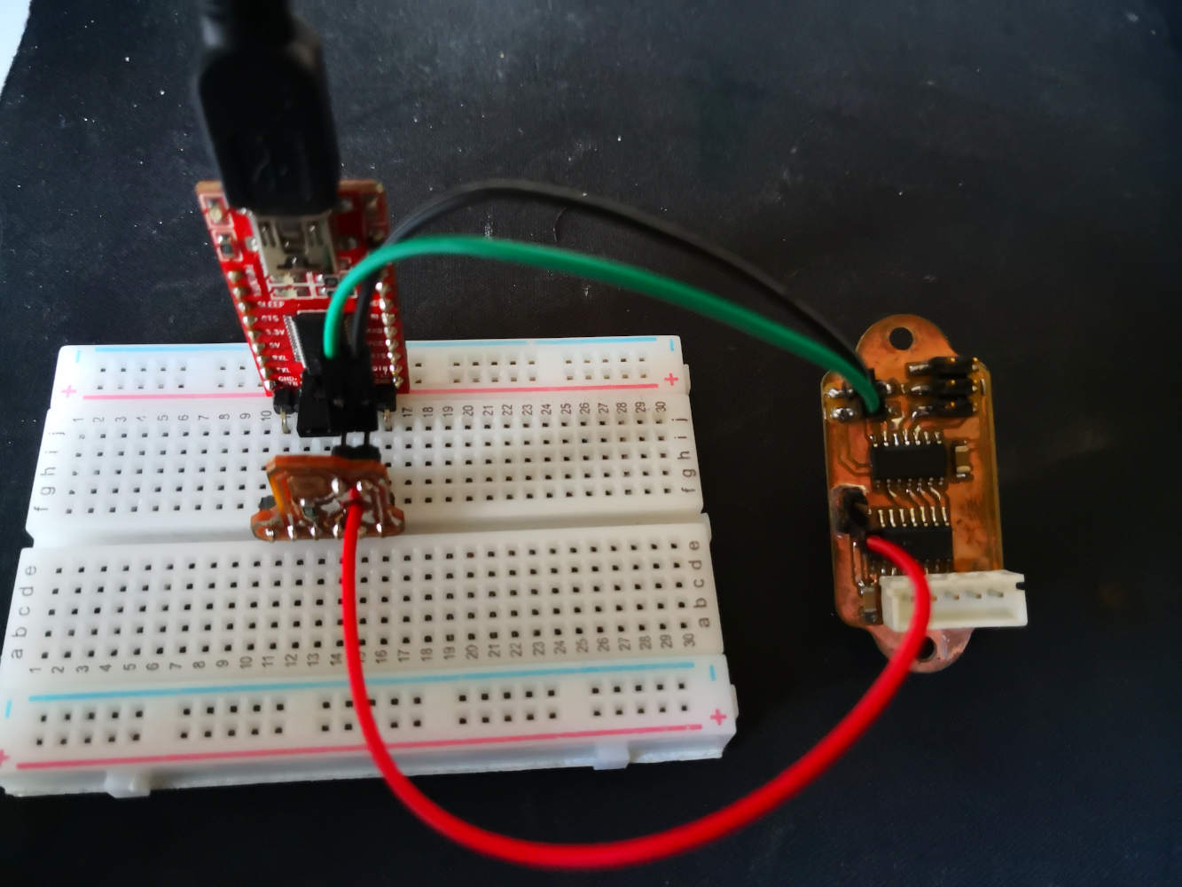
Now to upload an arduino sketch on your boards just follow this little step ^^ :
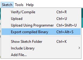
- On your ArduinoIDE go to sketch -> Export compiled Binary or
Ctrl + Alt + Sfor export your code as a .HEX file - Go on your Sketch folder ( you could use
Ctrl +Kon the IDE ) - Open a your windows terminal
- On your terminal type this
 python3 pyupdi.py -d your_processor -c your_port -b your_baud_rate
							-f your_hex -v
replacing the colored named by:- your_processor: The name of the MCU you use on your board ( for my project is "tiny1614" )
- your_port: The communication port where you have plug your programmer, you could see it on the arduinoIDE ( for me is "COM 4" )
- your_baud_rate: The speed of your upload communications ( i'm gonna use "57600" )
- your_hex: The complete path for your .HEX you previously Export ( Just click & drag it from your sketch files )
- Press enter to finish and upload your program.
More information about my ATTiny 1614 board Here